

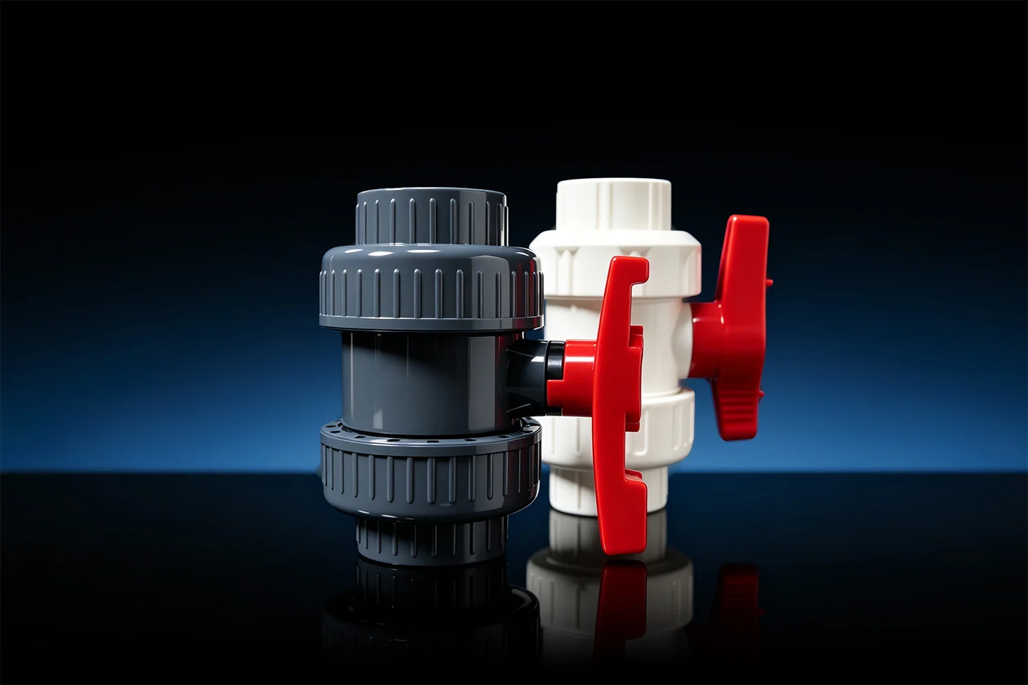
PVC-U ball valves and butterfly valves are widely used in water treatment, irrigation, swimming pool systems, chemical handling and industrial piping. Selecting the right valve requires more than choosing a nominal diameter. Operating pressure, fluid temperature, flow rate, pressure loss and required operating torque must all be considered.
This guide explains how to read pressure-temperature charts, torque charts and friction pressure loss charts for PVC-U valves.
Why Pressure and Temperature Must Be Considered Together
PVC-U valves are designed for specific pressure ratings under normal operating conditions. However, as the temperature of the fluid increases, the mechanical strength of PVC-U material decreases. For this reason, the maximum allowable operating pressure must be reduced at elevated temperatures.
Common nominal pressure ratings include:
| Pressure Rating | Maximum Nominal Pressure at Reference Temperature (20°C) |
|---|---|
| PN10 | 10 bar (approx. 145 psi) |
| PN16 | 16 bar (approx. 232 psi) |
For water or similar media at approximately 20°C, a PN16 valve may be used at up to 16 bar, while a PN10 valve may be used at up to 10 bar. At higher temperatures, the allowable pressure decreases according to the relevant pressure-temperature chart.
A valve should never be selected based on its nominal pressure rating alone. The final system pressure rating must be determined by the lowest-rated component in the pipeline, including valves, unions, fittings, flanges and pipe connections.
⚙️ Online PVC-U Valve Engineering & Selection Calculator
Result:
How to Read a Pressure-Temperature Chart
A pressure-temperature chart shows the maximum allowable operating pressure at different fluid temperatures.
To use the chart:
- Identify the actual operating temperature of the fluid.
- Find the temperature on the horizontal axis.
- Move upward until reaching the applicable PN curve.
- Read the maximum allowable pressure from the vertical axis.
- Confirm that the system operating pressure remains below this value.
For example, a valve that is rated PN16 at room temperature may require pressure derating when the operating temperature rises to 40°C or above. At temperatures close to 60°C, the allowable working pressure may be significantly lower than the nominal pressure rating.
Pressure-temperature charts are generally based on water or similar media and a specified design service life (e.g., 25 years). For corrosive chemicals, elevated temperatures, cyclic pressure or special media, the valve manufacturer should be consulted before final selection.
Ball Valve Operating Torque
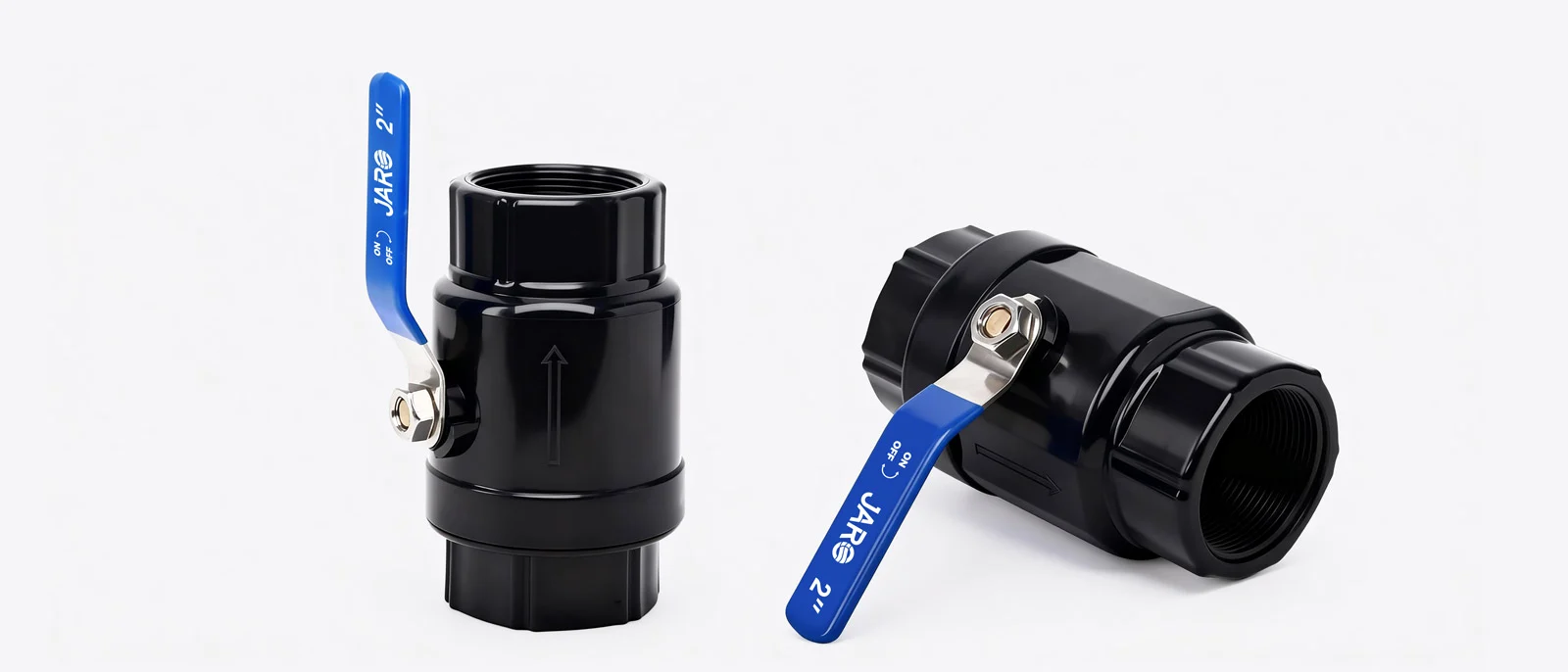
Operating torque is the rotational force required to open or close a valve. It is commonly expressed in Newton metres (N·m).
As valve size increases, the torque required to operate the valve also increases. Small manual ball valves may require only a low operating torque, while larger valves may require a longer handle, gearbox, pneumatic actuator or electric actuator.
| Nominal Size | Typical Ball Valve Operating Torque |
|---|---|
| DN10–DN15 | Approx. 0.5 N·m |
| DN20 | Approx. 1.5 N·m |
| DN25 | Approx. 2.5 N·m |
| DN32 | Approx. 5.5 N·m |
| DN40 | Approx. 7 N·m |
| DN50 | Approx. 10 N·m |
| DN65 | Approx. 20 N·m |
| DN80 | Approx. 26 N·m |
| DN100 | Approx. 28 N·m |
These values should be used as a selection reference. When choosing an actuator, additional safety margin should be applied to account for seal friction, aging, deposits, infrequent operation and actual service conditions.
What Is Friction Pressure Loss?
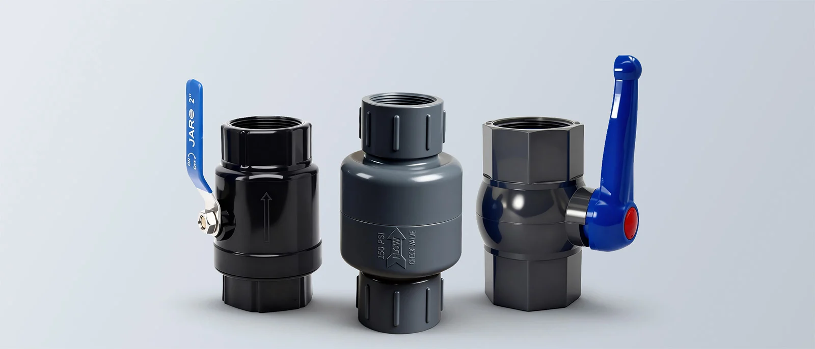
Friction pressure loss is the reduction in pressure that occurs as fluid flows through a valve. Even when a valve is fully open, the valve body and internal flow path create resistance.
Pressure loss depends mainly on:
- Flow rate
- Nominal valve diameter
- Valve design
- Fluid temperature and viscosity
- Valve opening position
- Fluid condition, including suspended solids or deposits
At the same flow rate, a smaller valve normally produces a greater pressure loss than a larger valve. As flow rate increases, pressure loss also increases.
To read a friction pressure loss chart:
- Locate the required flow rate on the horizontal axis.
- Move upward to the line for the selected valve diameter.
- Move horizontally to the vertical axis.
- Read the expected pressure loss in bar or psi.
For systems with demanding flow requirements, selecting an undersized valve may result in excessive pressure loss, reduced downstream flow and increased pump energy consumption.
Butterfly Valve Torque and Pressure Loss
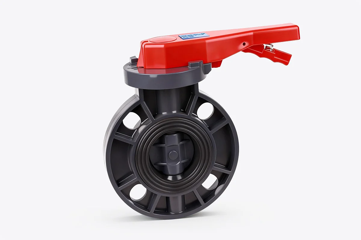
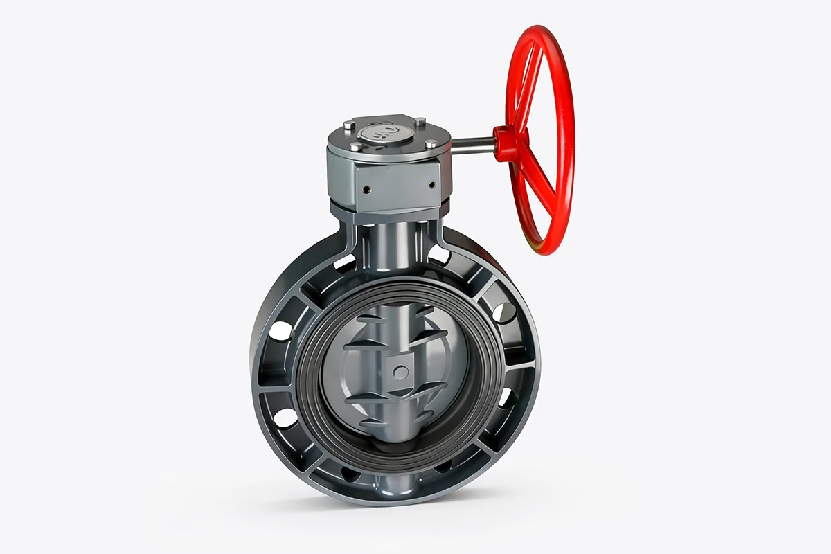
Butterfly valves are often selected for larger-diameter pipeline systems because they offer a compact installation size and efficient shut-off control. However, the disc remains in the flow path, which means the flow resistance and pressure loss can be influenced by the valve opening position.
Typical operating torque values for PVC-U butterfly valves at a 10 bar reference condition are shown below:
| Nominal Size | Typical Butterfly Valve Operating Torque (at 10 bar) |
|---|---|
| DN50 | Approx. 10 N·m |
| DN65 | Approx. 15 N·m |
| DN80 | Approx. 23 N·m |
| DN100 | Approx. 30 N·m |
| DN125 | Approx. 40 N·m |
| DN150 | Approx. 55 N·m |
| DN200 | Approx. 80 N·m |
When a butterfly valve is fully open, the pressure loss is relatively low for its size. When the valve is partially open, the flow passage becomes more restricted and pressure loss increases. For precise continuous flow control, the actual opening position and pressure loss should be checked against the manufacturer’s technical data.
Ball Valve or Butterfly Valve: Which Should You Choose?
| Selection Factor | PVC-U Ball Valve | PVC-U Butterfly Valve |
|---|---|---|
| Typical Size Range | Small to medium sizes (DN10–DN100) | Medium to large sizes (DN50–DN200+) |
| Flow Path | Usually more direct when fully open | Disc remains in the flow path |
| Manual Operation | Convenient for smaller sizes | Torque increases significantly at larger sizes |
| Installation Space | Requires more installation length | Compact wafer-style construction |
| Flow Adjustment | Suitable for isolation; not ideal for throttling | Can be used for rough adjustment, subject to evaluation |
| Automation | Suitable for pneumatic and electric actuators | Commonly used with gearboxes and actuators in larger sizes |
Valve Selection Checklist
Before selecting a PVC-U ball valve or butterfly valve, confirm the following engineering details:
- Fluid type and chemical compatibility.
- Operating temperature.
- Maximum operating pressure.
- Required flow rate.
- Allowable pressure loss.
- Nominal pipe diameter.
- Connection type (Socket, Threaded, Flanged).
- Manual, pneumatic or electric operation.
- Required actuator torque with safety margin.
- Applicable product specification and installation conditions.
Conclusion
Pressure-temperature performance, operating torque and friction pressure loss are essential factors in PVC-U valve selection. A properly selected valve improves system reliability, reduces energy loss and supports long-term operation.
For final selection, always refer to the technical data of the specific valve model and confirm the operating conditions with the supplier or manufacturer.
Need Assistance Selecting the Right Valve?
Need assistance selecting a PVC-U ball valve or butterfly valve for your piping system? Contact our technical engineering team for product recommendations and application support.