

When installing PVC valves, an intuitive rule of thumb often persists on job sites: the tighter the pipe fits into the socket, the safer the joint. For solvent-cement connections, however, this assumption is fundamentally flawed. The mechanical resistance felt during dry insertion has little to do with the long-term integrity of the cured chemical weld.
A dependable, leak-free joint relies on a holistic balance:
Core Joint Reliability Equation:
Precision Tolerances + Full Insertion Depth + Cement Redistribution + Controlled Curing + Continuous Fusion Interface
The engineering goal is neither an exaggerated taper nor substituting chemical bonding with a mechanical wedge. Instead, it centers on designing a controlled socket geometry that actively manages fluid adhesives and installation dynamics.
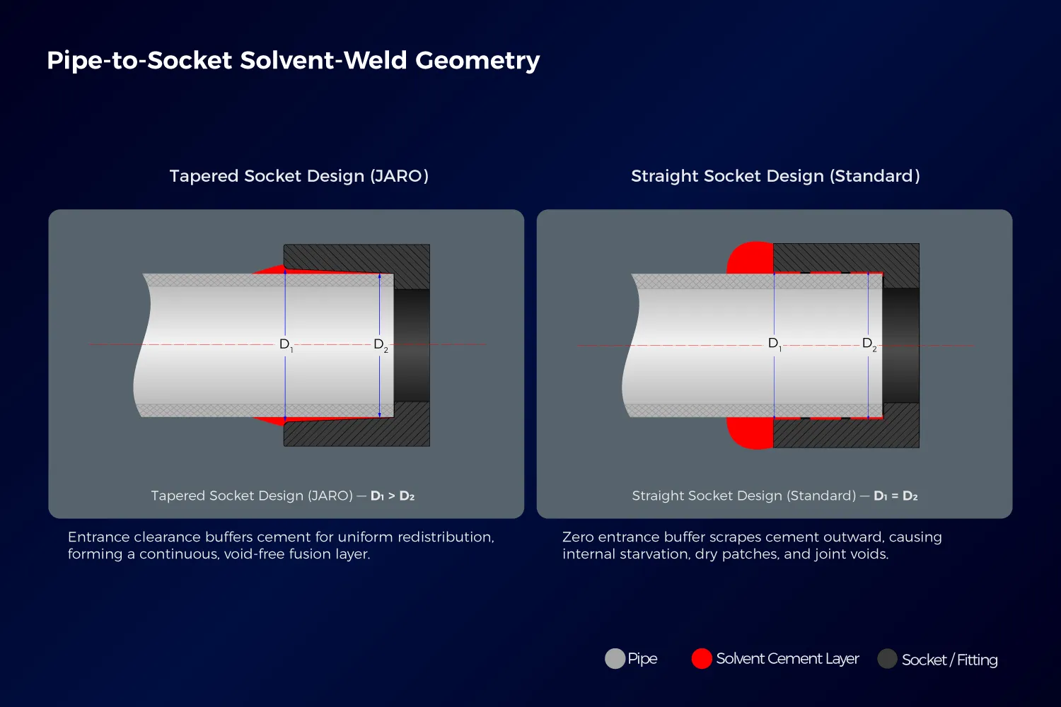
Controlled taper (D₁ > D₂) maintains uniform solvent cement distribution, while straight bore (D₁ = D₂) causes entrance cement scraping and internal voids.
1. The Common Misconception: Does a Tighter Fit Equal a Stronger Joint?
A solvent-welded joint does not rely on dry friction to hold the pipe in place. Instead, the solvent cement softens the mating surfaces of PVC-U or CPVC, chemically fusing the polymer chains across the entire engagement length according to standardized bonding practices like ASTM D2855.
If the socket entrance is excessively tight, it introduces several critical failure risks:
- Restricted Insertion: Prevents the pipe from reaching its designated insertion depth (stop line).
- Premature Cement Scraping: Forces the adhesive outward during the initial push, starving internal surfaces and forming dry spots.
- Axial Misalignment: Sharp entry resistance causes pipes to cock or seat eccentrically.
- Misleading Bead Formation: Creates a heavy external bead around the rim while leaving internal fusion incomplete.
Key Takeaway: Tighter fit ≠ Stronger joint
2. Does Pre-Cure Movement Indicate an Unsafe Fit?
Not necessarily. Within engineered manufacturing tolerances, a slight, perceptible play near the entrance is the direct result of controlled entrance clearance. This buffer zone accommodates the initial volume of solvent cement, preventing it from being wiped away before the pipe reaches deeper engagement.
It is critical to differentiate engineered clearance from actual defects:
- Engineered Clearance: A subtle, calibrated tolerance before curing that facilitates adhesive redistribution. It in no way reduces post-cure tensile or burst performance.
- Excessive Slop / Mismatched Sizing: Noticeable radial wobble or bottoming out without guidance. This typically indicates a standard mismatch (such as connecting ASTM/Schedule 40 pipe into metric DIN sockets). For precise cross-standard verifications, always cross-check dimensions with the plastic valve and pipe O.D. standard chart.
Key Takeaway: Controlled clearance ≠ Loose fitting
3. Understanding D₁ > D₂: Socket Geometry Explained
In a controlled tapered socket, the entrance inner diameter (D1) is marginally larger than the inner seat diameter (D2). This micro-taper is subtle and calibrated—not an aggressive wedge fit.
| Design Parameter | Controlled Taper Socket (D₁ > D₂) | Parallel Bore Socket (D₁ = D₂) |
|---|---|---|
| Initial Insertion | Calibrated entrance clearance accommodates cement bead | Constant clearance; entrance provides zero material buffer |
| Insertion Dynamics | Cement progressively redistributes along the full socket depth | High risk of scraping adhesive outward at the entrance edge |
| Cement Interface | Continuous, void-free chemical fusion layer across joint | Susceptible to dry patches, air pockets, and joint voids |
| Pre-Cure Tactile Feel | Smooth initial engagement with micro-clearance at the rim | Feels tight almost immediately upon insertion |
| Design Logic | Controlled clearance + progressive chemical fusion | Uniform clearance + friction-dependent alignment |
4. The Engineering Objective: Fluid Material Management, Not Mechanical Wedging
The fundamental purpose of D1 > D2 geometry is fluid material management during assembly:
This design is not intended to swage pipe walls or create a seal solely via mechanical interference. In pressure systems, it provides the physical pathway necessary for solvent cement to wet and fuse mating surfaces uniformly without creating dry voids.
Fluid Management Law
“Entrance Clearance Buffer → Minimized Early Scraping → Controlled Redistribution → 100% Wetted Fusion Interface.”
5. Why a Large External Cement Bead Is Not Proof of Joint Quality
A heavy exterior bead around the socket face merely shows that excess adhesive was pushed out. It provides zero visibility into whether the inner half of the socket has achieved continuous fusion.
A rigorous joint inspection should always evaluate:
- Pipe insertion reaching the bottom stop depth.
- 360° circumferential bonding coverage without dry voids.
- Precise axial alignment without angular cocking.
- Adherence to ambient temperature cure schedules before system pressurization.
- Verified dimensional compatibility between pipe O.D. and socket I.D.
Key Takeaway: Visible cement bead ≠ Uniform internal bonding
6. Why Taper Angles Cannot Be Arbitrarily Increased
Socket geometry must stay strictly within the envelope defined by pipe tolerances, injection mold shrinkage rates, adhesive gap-filling limits, and international standards:
- If the entrance (D1) is too wide, an excessively thick cement layer results, leading to longer cure times, chemical softening risks, and axial skew.
- If the root (D2) is too narrow, insertion resistance spikes sharply, prematurely wiping away primer and cement before reaching the stop ring.
Mature valve engineering operates within a verified tolerance window rather than relying on extreme tapers.
7. Socket Interface Design Across JARO Ball Valve Lines
Socket reliability is integral to valve performance, whether in demountable double union systems or compact industrial units:
True Union Systems: JRV22 & JRV23 Series
In high-demand industrial and commercial installations, true union ball valves allow pipeline maintenance without dismantling pipe runs. Both the PVC-U Double Union Ball Valve JRV22 and its companion JRV23 series implement controlled socket geometry on their end connectors to safeguard joint integrity under operational stress. To understand how end connector stability prevents joint displacement during temperature fluctuations, read our guide on preventing leaks in PVC-U double union ball valves under thermal cycling.
Compact & Distribution Systems: Octagonal Ball Valves
The same controlled socket engineering applies across compact distribution valves where space and rapid installation matter. For standard distribution setups, the PVC-U Octagonal Ball Valve JRV03 provides consistent socket tolerance control across metric and imperial standards. In agricultural, municipal, or tight plumbing manifold configurations requiring transitions, the MxF Octagonal Ball Valve JRV05 combines solvent-cement socket tolerances with molded threading to maintain uniform joint integrity across diverse pipe connections.
Conclusion
A reliable PVC valve socket is not defined by how stiff it feels upon dry fit. Long-term piping performance comes from balancing dimensional tolerance, cement flow dynamics, proper insertion depth, and the integrity of the cured chemical bond. Tactile resistance at assembly is never a substitute for verified engineering; a fully engaged, void-free, and properly cured solvent weld is what delivers lasting pressure containment.
Need Precision-Molded Valves for Your Next Piping Project?
JARO Industry manufactures high-tolerance PVC-U and CPVC valves under strict ISO 9001 quality controls, with 100% hydrostatic shell and seat pressure testing for global B2B distribution and OEM branding.